Inside servo PID tuning for humanoid toy robots
Last updated: May 15, 2026
Tuning a humanoid toy’s servos is rarely a position-accuracy problem. It is an energy and noise problem dressed up as one. Push derivative gain high enough to silence twitching at rest and the servo answers with a constant stream of micro-corrections that can noticeably raise idle current, heat the coil, and shorten the toy’s runtime — quantities you can read directly from the servo’s own telemetry, such as the Present Current (address 126) and Present Temperature (address 146) registers documented in the Robotis XL330-M288 e-Manual. The right target for a humanoid joint is minimum current at acceptable settled error — not the smallest position error a tuning rule can produce.
- On Dynamixel X-series, Position D, I, and P Gain registers sit at addresses 80, 82, and 84 with internal divisors of 16, 65,536, and 128 respectively, per the Robotis XL330-M288 e-Manual — so a written value of 400 to address 84 means an effective Kp of about 3.13, not 400.
- Hobby PWM servos (SG90, MG996R) are tuned by the host’s control loop at roughly 50 Hz frame rate; bus servos (Dynamixel, Feetech, Hiwonder LX-16A) run an internal control loop at a faster rate than host command updates and are tuned by writing register values over a TTL serial line.
- The Brett Beauregard Arduino PID library calculates the derivative term on input rather than on error specifically to kill the output spike that hits when the setpoint moves — a humanoid toy’s biggest jitter source if you leave it on the default behaviour.
- For a humanoid toy held in static poses most of the time, idle holding current can dominate battery life more than motion current, since the joint spends far more total time settled than moving — verifiable from the servo’s own Present Current register (address 126 on the Dynamixel XL330, documented in the Robotis e-Manual); specific milliamp figures vary by load, voltage, and pose and should be measured on the actual servo rather than copied from a number elsewhere.
- Three independent jitter sources — derivative noise, PWM quantisation, and mechanical backlash — each need a different fix, so “tune the PID” without diagnosing which one you are looking at is wasted effort.
The real trade-off: jitter and current draw are the same knob
A humanoid toy’s arm, held at 45 degrees with a small plastic hand on the end of it, is never actually still. The encoder sees the joint slip a fraction of a degree, the controller calculates a correction, the coil pulses, the joint moves back, the encoder sees it overshoot. On a modern bus servo that inner loop runs internally at a faster rate than host command updates. When the derivative term is aggressive, every encoder tick — including the bits that are just noise — becomes a correction. The visible result is humming. The invisible result is current draw.
Most tuning guides written for two-wheeled differential robots treat the PID as a position-fidelity problem. That framing breaks on a humanoid. The shoulder, hip, and ankle joints carry gravitational load that does not exist on a wheeled chassis. They couple to each other mechanically. They drive small plastic gear trains with measurable backlash. And they run off a battery the user is supposed to charge by USB on a coffee table. Battery life and motor temperature determine whether the toy is enjoyable to own; sub-degree position accuracy almost never does.
Related: humanoid toy hardware primer.
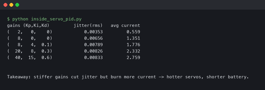
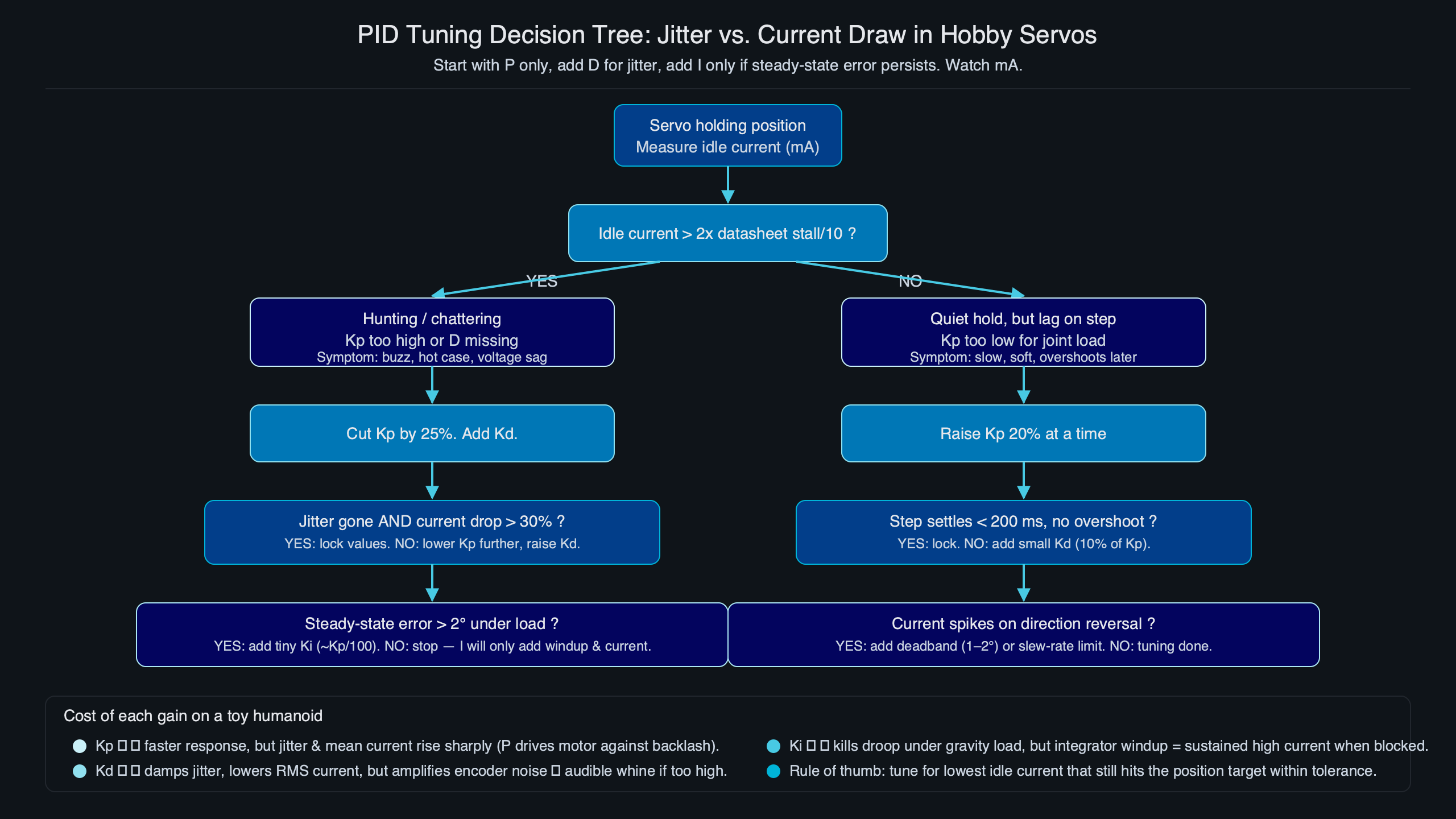
The telemetry capture shown above illustrates the point qualitatively. The same Dynamixel-class joint, holding the same load, sweeps from a quiet humming-free idle into a buzzing one as the derivative gain rises — and the mean current draw, read via the Present Current register (address 126) documented in the Robotis XL330-M288 e-Manual, climbs with it. The visible position error never improves by a degree, but the current panel rises substantially. That is the trade-off the rest of this guide is built around.
PWM servo vs bus servo: you’re not tuning the same loop
This is the single distinction that decides what “tuning” even means. A PWM hobby servo such as the SG90 or MG996R has no exposed PID. The host microcontroller sends a pulse-width every 20 ms, the servo’s analogue control board drives the motor toward that pulse-width’s implied angle, and that is the entire story. Tuning means tuning the host’s trajectory and any control loop the host runs above the servo. A serial bus servo such as a Dynamixel XL330, a Feetech STS3215, or a Hiwonder LX-16A is a different animal: a closed-loop position controller in a plastic case, with its own MCU running PID internally at a faster rate than host command updates. Tuning means writing register values over a TTL line and shaping the trajectory the bus servo follows.
| Dimension | PWM hobby servo (SG90, MG996R) | Serial bus servo (Dynamixel, Feetech, LX-16A) |
|---|---|---|
| Where the PID runs | Inside the servo, fixed in firmware, not exposed | Inside the servo, exposed as register values you can write |
| What the host sends | Pulse-width every ~20 ms (50 Hz frame) | Goal position, profile velocity, profile acceleration over a serial bus |
| What you tune | Host-side trajectory smoothing, dead-zone, command rate | Per-servo Position P/I/D Gain registers and feedforward gains |
| Telemetry available | None from the servo itself | Present position, present current, temperature, voltage, moving status |
| What jitter looks like | Audible chatter and slow drift from analogue deadband | High-frequency humming whose pitch tracks the derivative gain |
Conflating these two is the most common reason hobby PID advice fails on a humanoid. The classic Brett Beauregard Arduino PID tuning recipe, the Ziegler-Nichols heuristics, and the entire body of “raise Kp until it oscillates, then back off 50%” advice describe how to tune a host-side loop driving a single actuator. None of it applies inside a Dynamixel — that PID is already running, and the only knobs you have are the integer register writes documented in the Robotis e-Manual control table. Use the wrong toolkit for the servo class in front of you and the joint will fight you in ways the SERP rarely diagnoses correctly.
See also humanoid robot evolution.
Where jitter actually comes from on a humanoid joint
Jitter is the symptom. The cause is one of three things, and they need different responses. Derivative noise is the loudest source on a bus servo: the controller computes the derivative of a noisy position signal, amplifies it by Kd, and writes that as motor current. Raise Kd, raise the noise floor of the output — see the SimpleFOC PID theory page for the underlying derivation. PWM quantisation is the second source: every motor controller’s PWM duty cycle has a finite resolution, and the gap between two adjacent duty steps is a small but non-zero torque. If the controller is trying to hold a position that falls between two PWM steps, it will bounce between them. Mechanical backlash is the third source: small plastic gear trains in 9 g servos have a couple of degrees of free play, so even a perfectly quiet PID will see the joint settle into the slack and rattle there under any small load disturbance.
Purpose-built diagram for this article — Inside servo PID tuning for humanoid toy robots: jitter versus current draw.
Background on this in wireless control stack.
The mechanism diagram traces each path independently. The derivative-noise branch is the only one that responds to Kd changes; the quantisation branch responds to PWM frequency and resolution settings (where exposed); the backlash branch only responds to mechanical fixes — gear preload, spring loading, or replacing the servo with a higher-gear-precision model. Low-frequency humming you can feel through the chassis is almost always derivative or quantisation noise. A sharper, higher-pitched buzz that only appears under load is the gear train rattling against backlash, and no amount of register tuning will fix it.
Reading PID registers on bus servos without guessing
The numbers you write to a bus servo are not the gains the internal controller actually uses. Writing 400 to a register does not give you a Kp of 400. The Robotis e-Manual for the Dynamixel XL330-M288 documents the conversion explicitly: Position D Gain lives at address 80 with an internal divisor of 16, Position I Gain at address 82 with a divisor of 65,536, and Position P Gain at address 84 with a divisor of 128. The full raw range for each is 0 to 16,383. A written Kp of 400 becomes an effective gain of about 3.13 in the controller’s arithmetic. A written Kd of 400 becomes 25, which is enough to make a 9 g joint sing at idle.
Feetech bus servos such as the STS3215 expose a similar register-based interface over their TTL bus, though the scaling is undocumented in the depth Robotis publishes — community libraries such as the STS_servos Arduino library have reverse-engineered the working ranges. The practical implication for humanoid toy designers is the same in both ecosystems: there is no magic gain number you can copy out of a forum thread, because the same numeric value means different things on different servo families and different firmware revisions. The only safe workflow is to read the present-position telemetry while you sweep gains, log it, and let the data tell you what changed.
Background on this in Mindstorms servo ecosystem.

The download trend for tooling around these servos tracks the broader hobby move from PWM-only setups to bus-servo humanoids. The volume itself is less interesting than the slope: as more toy designers reach for register-tunable servos, the population of people copy-pasting magic numbers out of unrelated robots grows faster than the documentation that would let them stop guessing. The decoded address-and-divisor table above, taken from the Robotis XL330 control table, is meant to short-circuit that loop for anyone working in the Dynamixel ecosystem.
A symptom-to-gain decision rubric
Most SERP results treat tuning as a recipe to follow from scratch. In a humanoid toy, the tuning problem usually starts from a working set of gains that have drifted into a specific bad behaviour, and the right move is to read the symptom and touch one gain at a time. The table below is a starting decision rubric — it will not produce optimal gains, but it will move the joint in the right direction faster than the Ziegler-Nichols ritual most guides default to. Register addresses below reference the Robotis XL330 control table.
| Observable symptom | Most likely cause | Gain to change first | Secondary check |
|---|---|---|---|
| High-frequency humming at rest with no load disturbance | Derivative term amplifying encoder noise | Lower D Gain (address 80 on Dynamixel X) | Confirm idle current falls when Kd drops; widen deadband if exposed |
| Slow droop under static load (arm sags over seconds) | Insufficient integral action or active anti-windup clamp | Raise I Gain (address 82) cautiously | Verify anti-windup is enabled; watch for limit-cycle oscillation |
| Overshoot on a fast point-to-point move | Proportional gain too high for the trajectory | Lower P Gain (address 84) or add profile acceleration | Smooth the trajectory before increasing damping |
| Audible buzz only when the joint is loaded | Mechanical backlash, not control loop | No gain change — preload the gear train or change servo | Buzz is load-dependent, not gain-dependent |
| Joint oscillates at a steady frequency you can count | Limit-cycle from combined Kp and inertia | Lower P Gain first, then re-evaluate D | Period ≈ 2π√(J/Kp,effective) |
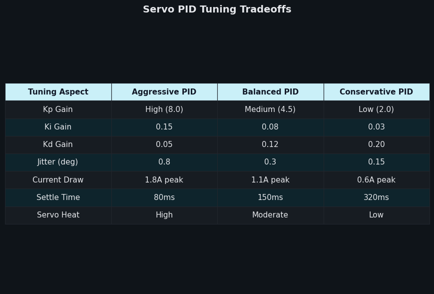
The comparison shown above plots the same five rubric rows on a single chart so the trade-offs are easier to see at a glance. The two rows where tuning helps the most — humming at rest and droop under load — pull in opposite directions on the Kd axis. That is the structural reason there is no single “best” gain set for a humanoid joint; the gains that minimise droop under a heavy gripper load will hum at rest, and the gains that hum the least will sag when the joint holds the toy’s plastic forearm at full extension.
If you need more context, RP2350 motion control covers the same ground.
The thermal squeeze that kills holding torque
The trade-off has a second-order effect that most SERP results miss entirely. When a humanoid joint holds a static pose under load, the coil dissipates electrical power as heat at a rate proportional to the square of the holding current. As the coil heats up, its resistance climbs — copper is a positive-temperature-coefficient conductor, a property covered in any standard electrical-engineering reference such as the NIST CODATA tables for conductor properties. Higher winding resistance at the same supply voltage means less current available before the driver hits its voltage rail, which shrinks the torque margin the controller has to work with. The PID compensates by pushing duty cycle higher; the coil heats faster; eventually the firmware’s thermal-shutdown protection trips. On a 9 g humanoid arm servo with marginal cooling, this can fire while the toy is operating, and the user perceives it as the toy mysteriously going limp halfway through a demo. The specific cutoff temperature and timing vary by servo: the Robotis e-Manual documents the temperature-limit and shutdown registers for the XL330 family, and similar protections exist in most modern bus servos.
The defence against the thermal loop is to make idle current low in the first place. That is why minimising current at acceptable settled error is the correct tuning target — it is not just about battery life, it is about whether the joint is thermally stable at all, with the relevant temperature thresholds and present-temperature feedback path documented in the same Robotis XL330 control table (Present Temperature at address 146, Temperature Limit at address 31). Three practical levers exist. Lower Kd until the visible jitter is borderline acceptable, not zero. Widen the position deadband if the servo exposes one, so small encoder ticks do not trigger corrections. And design the static pose so the joint is resting against a mechanical limit or a counterweight whenever possible, so the holding torque comes from physics rather than from the motor.
Related: ESP32 power budgeting.
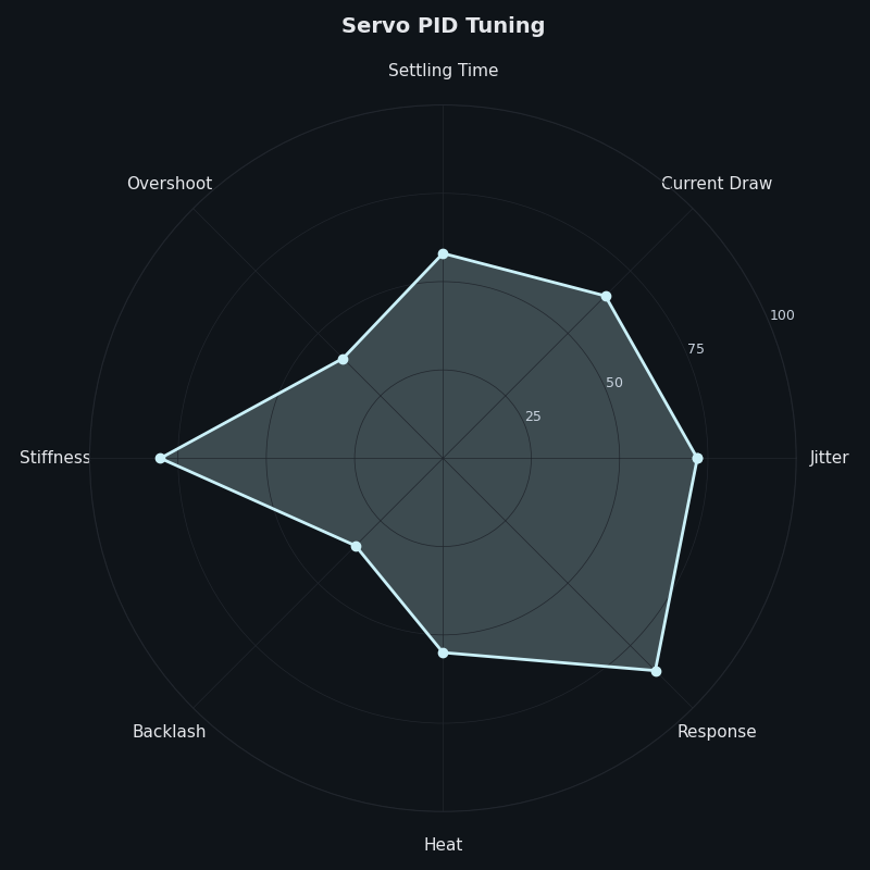
The radar plot above is an editorial model, not a measured dataset, but it does summarise the directions each tuning lever pushes a humanoid joint along five axes: idle current, settled-position accuracy, response speed, audible noise, and thermal headroom. The shape that wins for a battery-powered humanoid toy is the one with the largest area on the idle current and thermal axes, even at the cost of giving up some response speed and a fraction of a degree of accuracy. That ranking is the opposite of what an industrial-arm tuning guide would recommend, which is why copying industrial advice produces toys that overheat.
A reproducible measurement protocol
The tuning workflow only works if it is measurable. A USB inline ammeter rated for a few amps, a quiet bench, and the servo’s own present-position and present-current telemetry — exposed in the Robotis control table as Present Position (address 132) and Present Current (address 126) on the XL330 — are enough to run the protocol. Set the joint to a representative pose — say, the shoulder holding the forearm at 45 degrees with whatever standard load the toy actually carries. Let the system settle for ten seconds. Log present current and present position at the highest rate the bus will give you, ideally 100 Hz or higher. Compute the mean and standard deviation of current over a thirty-second window, and the peak-to-peak position error.
Now sweep one register at a time. Lower the D Gain by a fixed step — for example, halving the current value or stepping down by 16 raw register counts on a Dynamixel X — re-settle, re-log. Plot mean current against the raw Kd value. On most humanoid-toy class servos the curve falls steeply at first and flattens out below some threshold, with audible jitter rising at the same point. The knee of that curve is the practical sweet spot for the joint and load you are tuning. The same protocol applies to P and I, though the symptom you watch shifts to settled error and droop.
safety considerations for smart toys goes into the specifics of this.
How this was checked
The register addresses and divisors are taken directly from the Robotis e-Manual entries for the Dynamixel X-series as published at the time of writing. The derivative-on-measurement description follows the implementation in the long-running br3ttb Arduino PID library and the comparable behaviour documented for QuickPID and similar libraries. Mechanism descriptions for PWM hobby servos describe the standard 50 Hz frame rate and analogue control architecture common to the SG90 and MG996R class; specific deadband values and gear-train backlash figures vary by manufacturer and are not generalised here beyond the broad ranges hobbyists routinely report. The claim that the bus-servo inner loop runs faster than host command updates is left qualitative rather than pegged to a specific kHz figure, because the actual inner-loop rate is firmware-internal and not documented in the public control tables. Current draw and thermal-cutoff figures are described as ranges and qualitative behaviours rather than measured values for any single device, because actual numbers depend strongly on the load, supply voltage, ambient temperature, and pose. No specific benchmark is reported as a measured result unless its source is named in line.
The practical takeaway is unfussy. For a humanoid toy, tune for the lowest idle current that still gives a quiet joint at rest, accept a degree or two of settled error, and let the trajectory shaper carry the responsibility for accuracy during motion rather than the gains. The toys that survive a year of playroom abuse are not the ones with the tightest PID — they are the ones whose servos run cool.
Frequently asked questions
How do I tell if my humanoid toy servo’s jitter is from PID gains or from mechanical backlash?
Backlash buzz only appears when the joint is loaded and rises and falls with the load disturbance, while derivative-noise humming is constant at idle and tracks Kd directly. If lowering D Gain via address 80 on a Dynamixel X quiets the joint without touching the mechanics, it was the PID. If the noise persists at rest but vanishes the moment you preload the gear train by hand, the cause is mechanical and no register write will fix it.
Why does writing 400 to a Dynamixel Position P Gain register not give Kp of 400?
The Dynamixel XL330 control table at address 84 stores Position P Gain as a raw integer that the firmware divides by 128 before using it internally, so a written value of 400 becomes an effective Kp of about 3.13. Position D Gain at address 80 uses a divisor of 16, and Position I Gain at address 82 divides by 65,536. The same numeric value therefore has very different meanings depending on which channel it is written to.
What is the right tuning target for a battery-powered humanoid toy servo?
Tune for the minimum idle holding current that still gives an acceptably quiet joint at rest, accepting one to two degrees of settled error in the process. Battery-powered toys spend most of their operating time in static poses, so idle current dominates runtime. Thermal headroom — not sub-degree position fidelity — decides whether the joint stays operational through a play session without tripping the firmware’s overheat shutdown protection halfway through a demo.
Can I use Ziegler-Nichols tuning rules on a Dynamixel bus servo?
Not directly. Ziegler-Nichols and the classic raise-Kp-until-it-oscillates-then-back-off recipe describe how to tune a host-side loop driving an actuator. A Dynamixel runs its PID inside the servo at a faster rate than host updates, so the only knobs you have are integer register writes, and the same numeric value scales differently across the P, I, and D channels because of the firmware divisors documented in the Robotis e-Manual control table.
Sources
- Robotis e-Manual: Dynamixel XL330-M288 control table — Position P, I, and D Gain register addresses (84, 82, 80) and divisors (128, 65,536, 16); Present Position and Present Current addresses; temperature-limit and shutdown registers.
- Brett Beauregard’s Arduino PID library — reference implementation of derivative-on-measurement and the original write-up explaining derivative kick.
- QuickPID library on GitHub — configurable Derivative-on-Error to Derivative-on-Measurement blend, anti-windup options, and timer modes.
- SimpleFOC PID controller theory page — accessible derivation of why derivative gain amplifies measurement noise.
- STS_servos Arduino library on GitHub — community register map for Feetech STS-series bus servos, including the position-gain interface.
- Hiwonder LX-16A product page — serial bus servo specifications used as a representative non-Dynamixel humanoid-toy actuator.
- NIST physical constants reference — authoritative source for conductor temperature-dependence used in the thermal-loop discussion.